RaDAR – Field antenna comparisons

On my to do list: 

I’d certainly like to do signal strength comparisons between a coax fed inverted vee and an end fed antenna (No radials – just a short coax feed) at QRP levels. In particular on 40m.

The end fed will also be raised, at the same height above ground, as an inverted vee with the same orientation hoping there is no interaction between the two, a few meters apart….

I would require patient experimenters within a radius of 500 km.

The FT-817 does have a software controlled antenna switch so switching between antennas takes a second or two.

I could use a digital signal like PSK31 as a signal source to make it easier to read a S meter or better signal indicator, it doesn’t have to be accurate, just an observation.

This experiment will put my mind to rest to know what best to use in the field as an on foot RaDAR operator which is my passion, no doubt.

73 de Eddie ZS6BNE

Rapid Deployment Amateur Radio

RaDAR – Signature image test

My son is coming to visit this weekend and we will be starting with the RaDAR promotional movie.

LTX_BFN

The following guidelines are applicable:

The true intent of RaDAR

RaDAR – Rapid Deployment Amateur Radio
Rapidly deployed, easily moveable (objects), amateur radio stations.

The concept of objects came from one of my initial RaDAR logo designs where the pyramid stood for fixed stations, the cube for portable stations and the blue ball for mobile or on foot stations.

A discussion group of Hams preferred the logo of the “on foot” operator. The colour scheme was chosen among many examples and it has since been accepted as the official RaDAR logo.

Everyone is included and each has a function. All objects rely on each other for a complete and effective communications structure but are able to operate independently.

The emphasis on RADAR is mobility or on moveable stations no matter what the object or category.

In 2013, mobility was built into the rules of the contest requiring stations to move after every five contacts. This applies to mobile and on foot operators only. (Fixed and portable stations could very well join in to test mobility and re-deployment!)

The RaDAR concept diagram was updated highlighting the aspects of RaDAR

• Promoting the use of standard calling frequencies

• Promoting the use of APRS facilities, digital communications and satellite communications.

A further idea regarding the on foot operators is promoting stealth operations (Much like a fox in fox hunts) This is still relatively new and still needs to be developed.

RaDAR is not limited to any country.

The concept stays the same. Calling frequencies changed somewhat to accommodate all regions and regulations structures.

RaDAR is in full blossom with the dawning of a new year – 2013.

After many years, RaDAR has finally become what it was meant to be. The concept has been refined and has become the guideline for ham radio communications throughout the various installations or deployments.

Right from the very beginning, RaDAR has catered for any station, be it fixed, portable stations in alternate buildings, field stations, various mobile stations and the ham radio operators on foot.

Much of the newer ideas, like the “one contact per kilometer moved” experiment done in 2012, combine with the RaDAR concept in whole to present a concept that not only provides excellent communication skills and knowledge but to enhance the fun aspect of RaDAR.

Much has been said about rapid re-deployment and movable stations and with the latest contest rules for 2013, RaDAR is even more so – exactly that.

That makes RaDAR extra special. 

73 de Eddie ZS6BNE
SARL member. Radio ZS Contributor. Licenced since 1975
Rapid Deployment Amateur Radio

radarlogoorangeonblackbnourl100


RaDAR – Experimental antennas

ZS6BNE Open Wire Fed RaDAR Antenna

An antenna for the not so perfect world

By Eddie Leighton ZS6BNE

The idea of using a random length open wire fed antenna is as old as amateur radio itself. “Ladder line” can be easily home brewed.

In the past, I did not have much success using G5RV’s and the ZS6BKW improved antenna maybe because I did not try hard enough! However, reading up on the Net on random length, open wire fed, multiband antennas, my interest was once again awakened, especially for RaDAR, where, in most cases, the antenna system and the operating environment are far from ideal.

Having always used a QRP transciever for HF RaDAR communications, namely the FT-817ND, and an Inverted Vee I found myself tuning the length of an 80 meter Inverted Vee during the recent RaDAR contest because I had cut the lengths for the CW portion of the band and the only activity on 80 meters at the time was on the SSB portion of the band, the very last 100 kHz! That meant cutting a reasonable length off each side for resonance that the 817 could give full power (5 Watts) output. Note the SWR indicator on the 817 was a great help here!

After that experience, it was time to invest in an ATU. The most ideal option I found was the LDG z817 Automatic ATU (QRP) and I have never looked back. Not only did it help to work into an Inverted Vee cut SLIGHTLY off frequency but it opened a world of other options which is what I’d like to share with you here.

The open wire feedline can look somewhat bulky and as you may have read, such a line should not come into close proximity of metal objects. For quite some time now, I’ve been using an “Eskom” telescopic pole as an antenna mast in the field. Nothing could be more of an insulator than such an item. Indeed if it fails that test (High voltage) then it is discarded which is why some become available. If you’re very lucky you can get one at a very good price. I was extremely lucky, Henry ZS1AAZ, gave his pole to me!

The mast was the basis for my idea. I didn’t like the “Bulky” open wire feedline, especially for RaDAR. Anything that is carried unnecessarily is a waste of backpack space!

All transceivers have unbalanced coax connectors and having the incompatability with open wire feedlines. Fortunately there is such a thing as a Balun and I had one, a LDG 4:1 Balun. This was the key, opening the doors to both worlds!

Antennas are really an exact science. We talk about impedance, resonance and the theory behind antennas can be quite frightening. We pay dearly for optimum antenna designs. RaDAR in the field puts one in a position far away from being exact. Effective communications using low power and using simple items at hand is the objective!

Then I had a simple idea which became a bigger idea.

I used cable ties to fix my 4:1 Balun to the fiberglass mast, securing two flex wires to the sides of the mast. The mast then became the open wire spacer. Initially the wire lengths were quite random. I estimated the mast, when extended, to be over 6 meters in height and added another 20 meters of wire for each leg of the dipole / Inverted Vee antenna. So in effect, each wire was about 27 meters in length (I added another meter of wire, for taste). Note, nothing is exactly cut here, except for the two wires being the same length (Balanced)).

Using my FT817 and z817 ATU, I found the antenna could be tuned quite easily, at the push of a button!  No longer do I need to worry about 1/2 wave resonant lengths and coax losses to the feedpoint. Although Inverted Vee’s always worked for me, this arrangement is a winner! Open wire fed, random length flat top works in Inverted Vee configuration too. Tested using 5W (FT-817ND/z817 ATU) yesterday. Comms good locally and into Natal on 40m. The antenna tunes on all bands 80 to 6m including 30m and WARC bands!

John Green commented, “Eddie neat tuned feeder multiband dipole, clever idea to use the fibreglass pole as the spacer for the ladderline at the bottom. I have just received some packets of ladderline clips, still to try them out”.

Vidi la Grange commented, “Eddie, I love this idea and also use a telescopic pole like yours. I added a small (hard to find) pulley to the top and also an aluminium plate to which I can clip 3 stay ropes”.

Indeed, on my “To do” list, I had to find a better way of “Joining” the feedline and the antenna main and came up with this idea.

RaDAR_Antennas

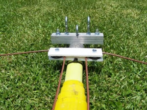
My comments on Facebook were, “29 January 2011 – My new RaDAR Multiband HF antenna. The open wire feeder tensioner system. Note, the “Pulleys” are made from rubber tap washers, the axle, a 6mm bolt and nylock nut. The flex wire used for the feeder / antenna, rides on these”.

Allen Wood commented, “Getting it spot on here Eddie. I have basically something similar but not happy with my feed line yet. The idea is to make the antenna as versatile as possible to suit any operating location and operating conditions”.

The secret to the open wire feedline tensioner system, was the use of Bungi cords. The following picture shows how this was done while the antenna was in a Delta loop configuration. The pulleys used were from an ineffective experiment done before the final “Tap washer” pulley idea! The metal pulleys worked much better here!

RaDAR_AntennasDeltaLoop

Delta Loop / Open wire feed, tensioner.

It was time to go into the field for antenna tests, the results were quite satisfactory! It turned out that, with one antenna, I could change to a different configuration quite easily, and quickly! The following were documented during the tests.

Antenna A – Multiband, open wire fed, doublet (Inverted Vee configuration).

Bands : 80m 40m 30m 20m 17m 15m 12m 10m

Open wire feedline length : +- 6 meters

Inverted Vee leg lengths : +- 21 meters , each

Antenna B – Multiband, inverted L (One leg of the doublet).

Two 20 meter lengths of flex wire were used as radials and connected to the earth terminal of the 4:1 balun.

Bands : 80m 40m 30m 20m 17m 15m 12m 10m

Inverted L leg length : 21 meters + 6 meters = +- 27 meters.

Antenna C – Multiband, open wire fed (Top), (NVIS) Delta Loop.

Bands : 40m 30m 20m 17m 15m 12m 10m

Open wire feedline length : +- 6 meters

Loop length : 21 + 21 meters = +- 42 meters. Doublet legs folded back to the base and joined.

Using an antenna system like this, gives me greater peace of mind, knowing under any circumstances, I will be able to communicate from the field.

RaDAR – Looking back

Rapid Deployment Amateur Radio

Hans, ZS6AKV and I were on our way back from Cape Town where we had attended the last RTA (Radio Technology in Action) program for 2009 and did our presentations there. The previous evening, during supper, we had discussed the latest initiatives in operating an amateur radio station in the field. We both agreed that it would be good to have a more professional name for the initiative.

It was at 12000 meters above ground, when Hans came down the isle, “Have you thought of a name yet Eddie?”, “No not yet … ” I replied and carried on thinking of a name. When we landed at Oliver Tambo airport, just after close on a two hour flight, I spoke to Hans, “How does RaDAR sound?“ , “Rapid Deployment Amateur Radio”.  RaDAR was born there and then!  Just to confirm, I sent an email to Hans the following morning asking if I could “Run” with the new name. Hans gave me his full support.

Originally the idea involved operating on foot and away from any vehicle or building but that excluded others also prepared to operate in a portable fashion and so the concept was refined. The following list gives an idea of what RaDAR entails.

Guidelines

It is desirable that the RaDAR operator be able to:

Operate an amateur radio station away from any building or vehicle but it is not a prerequisite.

Carry equipment, radios, antennas, masts, food, water and shelter to the final destination, in a vehicle , on foot or wheelchair.

Determine accurate position and grid square to 6 digits. A map or GPS can be used.

Provide power without relying on any third party. This can be in the form of solar panels, batteries or generators

Communicate in a professional, accurate and effective manner. Good voice procedure is imperative to get the message through, clearly and accurately.

Be self sufficient. The RaDAR operator should be able to operate on his own without relying on any third party.

RaDAR Subdivisions, “On foot”, “Mobile” and “Fixed”.

Logos

It’s always good to have a logo identifying the initiative, graphically. Many liked the “Radio Amateur” climbing a summit originally submitted by Mike, ZS6MEG. A comment from Andries, ZS6VL – “I like the association between hiking & ham radio. The concept behind RaDAR remains great.”

RaDAR has somewhat changed a little though expanding from an “On foot” operator to include other stations but emphasizing rapidly deployed, easily movable (OBJECTS), Amateur Radio stations.

Public relations

An activity like RaDAR can attract attention from people passing by. An idea to have a “Business card” on hand came to mind and so the RaDAR business card was born! This card includes all contact information.

Working together with other organizations

A valid question was asked on the SARL Forum by Jack Chomley VK4JRC. How does the RaDAR concept fit in with Hamnet? Hamnet is an organization. RaDAR is a concept supported by radio amateurs interested in being able to set up an amateur radio station anywhere and quickly! Hamnet could use radio amateurs with this type of readiness. Hamnet is affiliated to the SARL and the SARL supports the RaDAR concept! We’re all just one happy family

The first “Official” exercise

The 24th of September 2009 was Heritage day. Many RaDAR stations were active and signaled the early stages of the RaDAR Concept..